Appendix F — Reactor Heat Exchange
There are many different system geometries and heat exchanger types that can be used to add or remove heat from a reactor. In order to maintain a focus on the reaction, Reaction Engineering Basics problems involving heat exchange always use a perfectly mixed shell or jacket geometry through which a heat exchange fluid flows. The heat exchange fluid exchanges either sensible heat or latent heat, but not both. This appendix presents a brief overview on using this form of heat exchange with stirred tanks and tubular reactors.
F.1 Mass and Energy Balances on the Heat Exchange Fluid
Figure F.1 depicts batch, semi-batch and continuous stirred tank reactors with heat exchange. Figure F.2 similarly depicts a tubular reactor with heat exchange. The figures are not intended to convey the actual geometry of the reactors. The blue shading represents the reacting fluid within the reactor and the yellow shading represents perfectly mixed heat exchange fluid within the shell/jacket. The red line represents the wall separating the reacting fluid from the heat exchange fluid. Heat is transferred through this wall, while all other walls are assumed to be perfectly insulated.
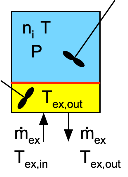
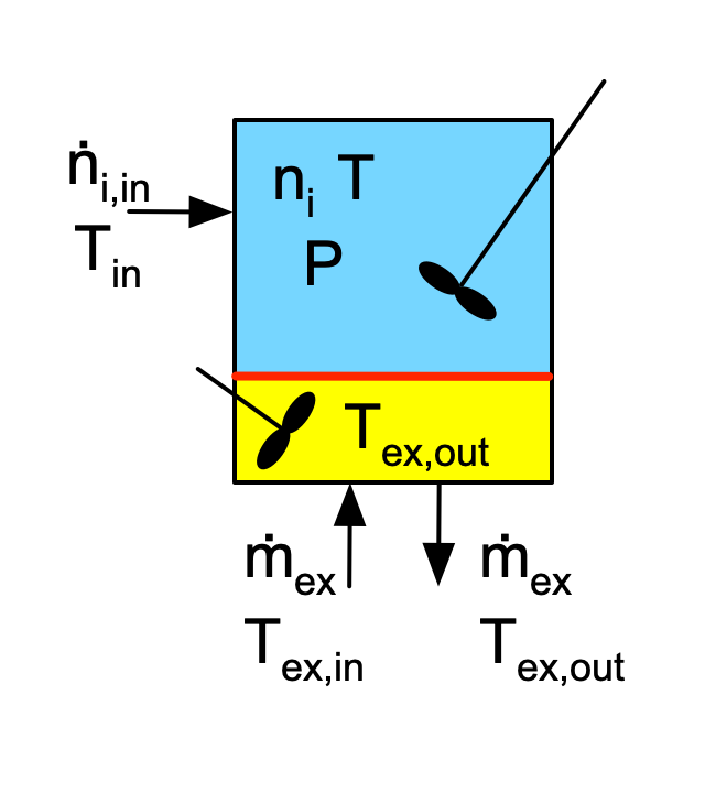
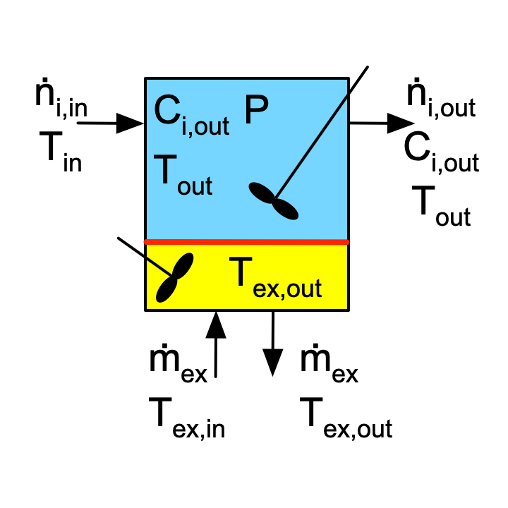
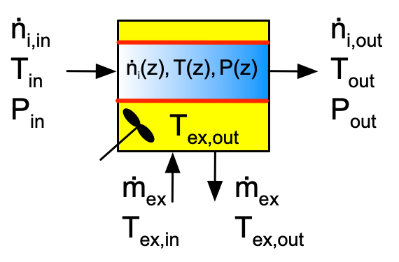
The inputs, outputs and flow patterns on the reaction side differ for each of the four reactors shown in Figures F.1 and F.2. However, the inputs, outputs and flow pattern on the shell/jacket sides of the four reactors are identical. Consequently, the mass balance and the energy balance on the heat exchange fluid is the same for all four reactors.
F.1.1 Mass Balance on the Heat Exchange Fluid
In Reaction Engineering Basics it is always assumed that there is no accumulation of mass in the reactor shell/jacket. Mass cannot be generated (other than by nuclear reactions), so there is no generation of mass within the reactor shell/jacket, either. Consequently the inlet and outlet mass flow rates are always equal, as shown in the figures. Note that the mass flow rate of the heat exchange fluid can vary with time, but any change in the inlet mass flow rate is accompanied instantaneously by an equal change in the outlet mass flow rate.
F.1.2 Energy Balance on the Heat Exchange Fluid
As noted, in Reaction Engineering Basics the heat exchange fluid undergoes either a temperature change or a phase change, but not both. The form of the energy balance is different for each of these situations.
Energy Balance for Exchange of Sensible Heat
With the assumptions of no mass accumulation in the shell/jacket and that the heat exchange fluid does not undergo phase change, an energy balance on the heat exchange fluid takes the form shown in Equation F.1.
\[ \rho_{ex} V_{ex} \tilde C_{p,ex}\frac{dT_{ex}}{dt} = \dot Q_{ex} - \dot m_{ex} \int_{T_{ex,in}}^{T_{ex}} \tilde C_{p,ex}dT \tag{F.1}\]
Energy Balance for Exchange of Latent Heat
Again assuming no accumulation of mass in the shell/jacket, and additionally assuming that the temperature of the heat exchange fluid does not change, an energy balance on the heat exchange fluid takes the form shown in Equation F.2. Typically, if the reacting fluid is being heated, the heat exchange fluid enters the shell/jacket as a saturated vapor. Within the shell/jacket, some fraction, \(\gamma\), of the heat exchange fluid condenses. This occurs at a constant and known temperature, namely, the boiling point. Less commonly, if the reacting fluid is being cooled by boiling the heat exchange fluid, the heat exchange fluid enters the shell/jacket as a saturated liquid, and within the shell/jacket, some fraction of the heat exchange fluid vaporizes.
\[ \frac{\rho_{ex} V_{ex} \Delta H_{\text{latent},ex}^0}{M_{ex}} \frac{d \gamma}{dt} = \dot Q_{ex} - \gamma \dot m_{ex} \frac{\Delta H_{\text{latent},ex}^0}{M_{ex}} \tag{F.2}\]
The maximum latent heat that can be provided or removed corresponds to complete condensation or complete vaporization of the heat exchange fluid. That is, the maximum amount of heat is exchanged with \(\gamma\) is equal to 1.
In both Equation F.1 and Equation F.2, the rate of heat input into the reacting fluid, \(\dot Q\), and the rate of heat input to the shell/jacket, \(\dot Q_{ex}\) are related as shown in Equation F.3.
\[ \dot Q_{ex} = - \dot Q \tag{F.3}\]
F.2 Heat Exchange with the Reacting Fluid in a Stirred Tank
In stirred tanks, Figure F.1, the reacting fluid is perfectly mixed. As a consequence, at any instant in time, the temperature, \(T\) is the same everywhere within the blue volume. Similarly, because the heat exchange fluid is perfectly mixed, the temperature, \(T_{ex}\) is the same everywhere within the yellow volume. Consequently, the instantaneous rate of heat transfer from the heat exchange fluid to the reacting fluid, \(\dot Q\), can be calculated using the overall heat transfer coefficient, \(U\), and the area, \(A\), of the wall separating the two sides of the reactor, Equation F.4.
\[ \dot Q = UA\left(T_{ex} - T\right) \tag{F.4}\]
Of the stirred tank reactor types, only CSTRs can operate at steady state. When a CSTR is operating at steady state, the derivative in either of the energy balances, Equation F.1 or Equation F.2, is equal to zero.
F.3 Heat Exchange with the Reacting Fluid in a Tubular Reactor
In a tubular reactor, the reaction side fluid is perfectly mixed in the radial direction, but it is completely unmixed in the axial direction. The gradient in the blue shading in Figure F.2 is meant to convey this point. As a consequence, the temperature difference between the reacting fluid and the heat exchange fluid changes along the length of the tube. That means that the rate of heat transfer also varies along the length of the tube. In Reaction Engineering Basics, it is assumed that the overall, local heat transfer coefficient, \(U\), is constant along the length of the reactor so that the total heat input to the reacting fluid from the heat exchange fluid is given by Equation F.5.
\[ \dot Q = \int_0^L \pi DU\left( T_{ex} - T \right)dz \tag{F.5}\]
As is the case for steady-state CSTR, when a tubular reactor operates at steady state, the derivative in either of the energy balances, Equation F.1 or Equation F.2, is equal to zero.
F.4 Symbols Used in this Appendix
| Symbol | Meaning |
|---|---|
| \(\dot m_{ex}\) | Mass flow rate of the heat exchange fluid. |
| \(t\) | Time. |
| \(z\) | Distance from the inlet along the axis of a PFR. |
| \(A\) | Heat transfer area. |
| \(\tilde C_{p,ex}\) | Heat capacity at constant pressure per unit mass of the heat exchange fluid. |
| \(D\) | Diameter of a PFR. |
| \(L\) | Length of a PFR. |
| \(M_{ex}\) | Molecular weight of the heat exchange fluid. |
| \(\dot Q\) | Rate of heat transfer into the reacting fluid. |
| \(\dot Q_{ex}\) | Rate of heat transfer into the heat exchange fluid. |
| \(T\) | Temperature of the reacting fluid. |
| \(T_{ex}\) | Temperature of the heat exchange fluid within the perfectly mixed jacket or shell/jacket. |
| \(U\) | Overall heat transfer coefficient. |
| \(V_{ex}\) | Volume of heat exchange fluid within the reactor shell/jacket. |
| \(\gamma\) | Fraction of the heat exchange fluid that undergoes phase change within the reactor shell/jacket. |
| \(\rho_{ex}\) | Density of the heat exchange fluid. |
| \(\Delta H_{\text{latent},ex}^0\) | Standard enthalpy change associated with the change in the phase of the heat exchange fluid. |